

ST-124-M3 inertial platform
Encyclopedia
Saturn V Instrument Unit
The Saturn V Instrument Unit is a ring-shaped structure fitted to the top of the Saturn V rocket's third stage and the Saturn IB's second stage . It was immediately below the SLA panels that contained the Lunar Module. The Instrument Unit contains the guidance system for the Saturn V rocket...
, a 3 foot (0.9144 m), 22 feet (6.7 m) section of the Saturn V that fit between the third stage (S-IVB) and the Apollo spacecraft. Its nomenclature means "stable table" (ST) for use in the moon mission (M), and it has 3 gimbals.
Development
It was number 124 in a series of similar devices, including the ST-120 (used in the Pershing missile), the ST-90 (used on the Jupiter and on early Saturn I flights), and the ST-80 (used in the Redstone). They are descendants of the LEV-3 of the German V-2 rocket. The ST-124 was designed by Marshall Space Flight Center and manufactured by Bendix Corporation, Eclipse-Pioneer Division, in Teterboro, NJ. It took 9 men 22 to 24 weeks to assemble an ST-124, and 70 percent of that time was spent installing about 3,000 wires.Mission history
The ST-124 stabilized platform was part of the navigation, control and guidance system of the Saturn V. Data from the ST-124 were used by the Launch Vehicle Digital Computer (another Instrument Unit component) to compare actual flight data to programmed flight plans and to calculate guidance corrections. Though the ST-124 operated all during the mission, its data were not used for guidance while the vehicle was in the atmosphere, where it was subjected to high drag forces. In this region, basically the time of the first stage burn, the vehicle followed a simple preprogrammed flight plan.Internal details
The attitude of the vehicle was measured relative to a coordinate system that was fixed just prior to launch with the X coordinate vertical, the Z coordinate in the direction of the pitch maneuver (down range, roughly East), and the Y coordinate perpendicular to the other two, cross range, roughly South. At the heart of the ST-124 was a platform that was held in a fixed orientation; hence the name "stabilized platform". It is connected by three gimbalGimbal
A gimbal is a pivoted support that allows the rotation of an object about a single axis. A set of two gimbals, one mounted on the other with pivot axes orthogonal, may be used to allow an object mounted on the innermost gimbal to remain immobile regardless of the motion of its support...
s that allowed the vehicle to roll, pitch and yaw but the stable platform to be held fixed in space. It was being translated, of course, but did not tilt during flight.
The platform is stabilized by three gyros
Gyroscope
A gyroscope is a device for measuring or maintaining orientation, based on the principles of angular momentum. In essence, a mechanical gyroscope is a spinning wheel or disk whose axle is free to take any orientation...
mounted on it. One measured any rotations about the X axis, one about the Y, and one about the Z axis. They generated signals that were shaped in feedback circuits and sent back to torquers on the inner, middle and outer gimbals that exactly countered the rotations, nulling the gyro outputs and keeping the platform stable.
The inner gimbal also carries three accelerometers, two pendulums, and a pair of prisms. The accelerometers measured vehicle acceleration along the X, Y, and Z axes. Their outputs were used by the LVDC to measure actual vehicle motion, for the purpose of navigation. The pendulums were used to set the X axis exactly vertical, and the prisms were used to align the Y and Z axes, just before launch. The prisms reflected infrared beams sent into the ST-124 by a theodolite stationed 700 feet away from the launch pad. Commands from the theodolite were transmitted via cables to the vehicle, to torquers in the ST-124 to orient the stable platform toward the correct azimuth.
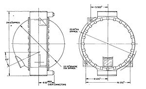
The gyros, accelerometers and pendulums contain almost frictionless nitrogen gas bearings. These required very precise machining and very small gaps between the bearing surfaces. Dimensions were held to tolerances of 20 microinches (0.5 µm), and the gap filled by the nitrogen is about 600-800 microinches. Nitrogen entered the gyros at about 15 psi and was vented to space via a pressure regulator in the bottom of the ST-124 that opened at 13 psi. The large silver sphere to the left of the ST-124 held the supply of nitrogen for the bearings.
The ST-124 includes many components made of anodized beryllium. This material was chosen for it stiffness, light weight, machinability and stability. The case of the ST-124 is a short cylinder, 7.5 inches high and 21 inches in diameter, made of beryllium. The ends of the cylinder are closed by two approximately hemispherical aluminum covers. The gimbals and several parts of the gyros and accelerometers are also made of beryllium.
In contrast to beryllium, which is lightweight, the rotors of the gyros are made of a very dense, strong material, Elkonite. This is a sintered form of tungsten, with about 10 percent copper, to make it machinable.
Heat generated by torquers and other electrical equipment inside the ST-124 was carried away by cooling coils built into the aluminum covers. A mixture of methanol and water at 15 degrees C was circulated through the coils. The internal temperature of the ST-124 stabilized at about 42 degrees C.