Process Flow diagram
Overview
The PFD displays the relationship between major equipment of a plant facility and does not show minor details such as piping details and designations. Another commonly-used term for a PFD is a flowsheet.
Typically, process flow diagrams of a single unit process
Unit process
A Unit Process is a step in manufacturing in which chemical reaction takes place, e.g, the oxidation of paraxylene to terephthalic acid is a unit process, the hydrogenation of vegetable oil to ghee is a unit process. In 1930 P.H. Groggins introduced Unit processes in order to classify and...
will include the following:
- Process piping
- Major bypass and recirculation lines
- Major equipment symbols, names and identification numbers
- Flow directions
- Control loops that affect operation of the system
- Interconnection with other systems
- System ratings and operational values as minimum, normal and maximum flow, temperature and pressure
- Composition of fluids
Process flow diagrams generally do not include:
- Pipe classes or piping line numbers
- Process control instrumentation (sensors and final elements)
- Minor bypass lines
- Isolation and shutoff valves
- Maintenance vents and drains
- ReliefRelief valveThe relief valve is a type of valve used to control or limit the pressure in a system or vessel which can build up by a process upset, instrument or equipment failure, or fire....
and safety valveSafety valveA safety valve is a valve mechanism for the automatic release of a substance from a boiler, pressure vessel, or other system when the pressure or temperature exceeds preset limits....
s - Flanges
Process flow diagrams of multiple process units within a large industrial plant will usually contain less detail and may be called block flow diagrams or schematic flow diagrams.
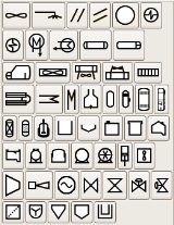
A PFD can be computer generated from process simulators (see List of Chemical Process Simulators), CAD packages, or flow chart software using a library of chemical engineering symbols.
Unanswered Questions

