
Number Five Crossbar Switching System
Encyclopedia
The Number Five Crossbar Switching System or 5XB switch, designed by Bell Labs
and made by Western Electric
, was in use in Bell System
telephone exchange
s from 1948 to the 1980s. Its principal use was as a Class 5 telephone switch, though variants were used as combined class 4/5 in rural areas and as a TWX switch.
5XB was originally intended to bring the benefits of crossbar switch
ing to small towns with only a few thousand telephone lines. The earlier 1XB urban crossbar was impractically expensive in small installations, and had difficulties handling large trunk groups. 5XB was converted to wire spring relay
s in the 1950s and otherwise upgraded in the 1960s to serve exchanges with tens of thousands of lines. The final 5A Crossbar variant in the early 1970s returned to its roots, being available only in sizes of 960 and 1920 lines, and generally delivered on one pallet rather than assembled on site as usual for larger exchanges.
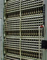
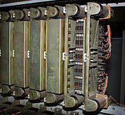
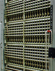 Line Link Frames (LLF) were tiers of 10x20 crossbar switches in two or more bays. The switches in the first bay had their horizontal multiples, or "banjo wires" cut in half, effectively dividing each switch into a Line Switch and a Line Junctor Switch. Each of the ten Junctor Switches had ten junctors on its ten verticals, and each of its ten levels was wired as a Line Link, to one of the ten line switches of the LLF. Thus, the Line Link Frame terminated 100 Junctors. Each Junctor had full availability to however many hundreds of lines there were, via the hundred Line Links. The number of lines, thus the Line Concentration Ratio (LCR) was engineered for the expected occupancy.
Each line switch in this first, mixed bay had nine lines on nine of its verticals, the tenth vertical being reserved for test purposes. In addition to the 90 lines on these switches, each LLF had at least one simple line switch bay, with ten more line switches carrying 200 lines. Thus the minimum size of a LLF was 290 lines for a line concentration ratio of 2.9:1. Optionally it had still another frame, with ten more switches and another 200 lines, and so forth up to a maximum Line Concentration Ratio of 5.9:1 since they all shared the same hundred Line Links. The line circuit was much like that in 1XB with a Line Relay for alerting the exchange to a trip condition, and the Vertical Off Normal contacts of the switch vertical serving as cutoff relay.
For control purposes the subscriber lines on the switches of the LLF were divided into Vertical Groups of fifty, being five line units on each of ten switches. Each Vertical Group was divided into five Vertical Files of ten lines, important because Class of Service, or Customer Group identification in later Centrex
offices, was shared by all ten lines in the Vertical File. Staff in Centrex offices spent much time standing on ladders, rewiring the Class of Service
data fields at the top of LLF.
Late in the career of 5XB, junctor group size and thus link efficiency of the largest offices was increased by the use of Auxiliary Line Link (ALL) Frames. The ALL was a bay with ten junctor switches, divided as usual into left and right halves. One half had on its levels the Line Links of an even numbered LLF and, on its verticals, the Junctors of the neighboring odd numbered one; the other half was vice versa. By this means, each LLF could use the Junctors of its mate, if the Marker failed to find an idle path on the first try. Since they were odd and even, their Junctors appeared on opposite sides of the Trunk Junctor Switches, thus giving access to the mate Trunk Links as well. Connections through the ALL were only used in heavy traffic periods.
relays or other active hardware, all such functions being assigned to trunk circuits. The basic design of the TLF had ten Junctor Switches with their horizontal multiples split in half, hence two hundred Junctors, and two hundred Trunk Links to the ten Trunk Switches. The banjo wiring of the Trunk Switch was not split, but a "discriminator level" trick devoted two levels to doubling the use of the other eight, thus allowing each Trunk Switch to connect sixteen trunks to its twenty Trunk Links. This resulted in the TLF having a 0.8:1 Trunk Concentration Ratio (TCR). This degree of deconcentration eventually turned out to provide too few trunk appearances for the variety of trunk types needed. The final 1970s 5XB offices had type C trunk switches with twelve levels, using two for discrimination, leaving a TCR of unity.
The TLF having twice as many links, Junctor Switches and Junctors as the LLF, there were always twice as many LLF as TLF. As first designed, the maximum number was ten TLF and twenty LLF, known as 10x20 and, at first rarely achieved. In the late 1950s, multiple Trunk Junctor switch bays (ETL and SETL) were added to give each TLF access to more Junctors. The first expanded version allowed each office to have 20x40, and in the 1960s the maximum reached 30x60. Development stopped at that point because the four stage layout was becoming progressively less efficient at greater sizes, and because the 1ESS switch
with eight stages was under development.
A Channel from a line to a trunk consisted of three links of switching fabric: Line Link, Junctor, and Trunk Link. In a 10x20 or larger office, ten Channels, numbered 0 to 9, were available from any line to any trunk. The Line Junctor Switch number and the Trunk Junctor Switch number were the same as the Channel number. Logic in the Marker compared the ten links of each kind to obtain a clear channel. The lack of a channel was called a mismatch and resulted in picking another trunk, or another line, or the use of the ALL where that existed, or giving up and letting the caller try again.
) or other peculiarity. Thus a TSPS trunk could give complete control to an operator, while an E and M signaling
trunk could do the kind of signaling required of a private long distance line, while a local outgoing trunk could be simpler.
Thanks to this more complex trunk circuit, outgoing trunks were selected by a quicker and more versatile method than the "sleeve test" previously used. Each trunk circuit provided a ground on a FT lead to indicate idleness. The FT leads for trunks in a particular group were cross connected to a FTC (Frame Test Common) lead for its Trunk Link Frame, to indicate that the TLF had one or more idle trunks in that group. The Route Relay in the Completing Marker connected sensor relays to all the Trunk Link Frames, allowing the Marker to choose a TLF that had an idle trunk and then connect to that trunk through the Trunk Link Connector (TLC) to choose one of those idle trunks. This two step method, along with the mixing of incoming and outgoing traffic, distributed traffic more evenly, thus alleviating the link congestion problems that often arose with earlier methods that restricted a trunk group to one or two outgoing switch frames.
This method was less efficient for coin phones, which needed special signalling. In urban areas, they were served by older exchanges that had separate junctors
for coin phones. Where the 5XB was the only exchange, a number of work-around methods were devised. POTS and coin phones shared the more complex and expensive coin trunks, or else separate routes were established, or coin trunks connected via tandems
including the 5XB itself acting as its own tandem. In this last case, the call had to use two connections through the switching fabric: One to connect the line to the coin supervision trunk and another to connect that trunk to the outgoing trunk.
It was also less efficient for tandem calls, since the fabric was unable to connect a trunk directly to a trunk. Instead each incoming trunk that had the ability to make tandem calls had to have a Line Link Frame appearance, as though it were a line. To avoid expense, incoming trunks were divided into groups, some of them having tandem ability and some not. This complication was avoided in places big enough to pay for a separate tandem switch.
 Connection of trunks to incoming registers
and outgoing senders was not through the four stage voice fabric. Rather it was through a dedicated single stage crossbar network known as Incoming Register Link (IRL) or Outgoing Sender Link (OSL) respectively. Registers and senders were in groups of ten, assigned one to each level of as many crossbar switches as were appropriate to the traffic they could handle. Different trunks were wired to different IRL or OSL depending on what kind of signaling they used; ie IRDP, IRRP (See Panel switch
), or IRMF
.
Previous systems used relays in the incoming trunk circuit to control ringing and to return busy tone. 5XB used a ringing Selection Switch (RSS), a crossbar switch with ten verticals, serving ten trunks. The various levels provided various tones, and ringing current of various durations and cadences (especially valuable for party line
s). Levels 0 and 1 were used as discriminating levels to set polarity for selective ringing on tip side or ring side
. An especially sensitive wire spring RT relay was used to detect off-hook
from a line being rung, release the RSS hold magnet, and engage the shielded supervision relay so reverse battery answer supervision
would be returned to the originating end.
 Call back, single train, and other sophisticated methods required more sophisticated controls, but they increased efficiency and became standard for later designs. 5XB also separated the registers for receiving digits, from the senders for sending them. This complication necessitated more transmission of data among the control circuits, but greatly shortened the holding time of senders and increased general efficiency and versatility without having to put the versatility into large, numerous and complex senders as in earlier systems
.
Originating Registers (OR) were wired to the Trunk Link Frame (TLF). In the original 5XB a marker, having been alerted to a trip condition, picked an OR by the same mechanism it would use to pick a trunk, identified a clear path between line and OR, loaded the OR with any information necessary for later processing (such as Line Equipment and Class of Service) and released itself. The OR then received the digits (rotary or tone), stored them in reed relay packs, and used the Pretranslator to determine how many digits to receive before calling in the Marker again to complete the call.
Larger 5XB were built in the 1960s with more Markers. To save money the markers were separated into two kinds: simple Dial Tone Markers (DTM) just to connect the line to the OR, and Completing Markers (CM), many times more complex and expensive, to complete the call to or from a trunk. CM had, among other features, the ability to translate the first 3 digits of a phone number (or 6 when using a separate Foreign Area Translator) to identify the correct outgoing trunks and handling.
Connectors, similar in purpose to the data buses inside a computer CPU, connected the Markers to the peripheral equipment. Each Connector was made up of large relays of 30 contacts each, to connect all the leads by which the Marker would exchange information and control signals. For example, each of the oblong reed packs in an OR would have to be connected by five leads through the Originating Register Marker Connector, to transmit the two-out-of-five code
representing one dialed digit. For speed, transfer was entirely parallel, requiring many large relays to connect so many wires. Connectors that responded to a peripheral circuit's request for action were named with the name of the requesting circuit and "Marker", as in ORMC or IRMC. Connectors whose use was requested by a Marker were named only for the circuit to which they connected, as in Outsender Connector, Line Link Connector, and Trouble Recorder Connector.
One of the drawbacks of step by step and other early systems is that the preference for choosing trunks or selector links was fixed, and the most preferred links are used more often, with the result that the same faulty hardware would block repeated call attempts until it was removed from service. 5XB markers were designed to rotate preferences in such a way that it was highly unlikely that the same circuit elements would be used in the next call. Thus, if a call encountered an equipment problem, a second try would probably succeed.
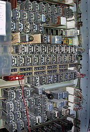
Partly because of this deliberate design decision to help shield users from component failures, the few, shared markers contained a great deal of self-checking circuitry. This was feasible because there were only a few markers, and beneficial because their correct function was critical. Digit codes, for instance, were checked to ensure that exactly two out of the five lines were activated. When the built in self test circuits of a marker detected an error, a large punch card was produced at the test station recording the failure in order to assist the switchmen in detecting it and diagnosing the source. The card punch, with some cards, is visible in the lower left of the test frame picture below.
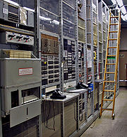 To a greater degree than in previous designs, test facilities were centralized into a Master Test Frame. This complex piece of equipment was wired into all common control equipment, and could for example automatically exercise the abilities of digit receivers to operate at different speeds, voltages and other parameters. MTF could select particular outgoing trunks, including testing the ability of the Markers to select different lines to particular trunks. This test facility became more valuable as Centrex
, Direct Distance Dialing
and other innovations brought more complications to the tasks of translation and trunk selection. For lines, MTF could test translations and conduct voltmeter tests to detect impedance imbalances and other electrical conditions that could impair service.
Other test equipment included a Line Insulation Tester and an Automatic Trunk Tester, for items whose numerosity and simplicity lent themselves to automatic testing. An automated AMA translator tester checked for miswiring that could bill one line to another. A non automated Outgoing Trunk test panel allowed voltmeter checks on trunks to distant offices, freeing the MTF from this tedious job. Each Outgoing Trunk was represented by two jacks: one for test access for the voltmeter and one for Make Busy. MTF was able to override Make Busy when necessary.
Also taking advantage of the superior versatility of 5XB, Centrex
was invented as a service package. Later Stored Program Control exchange
s allowed more extensive service features. Autovon
originally used a four wire version of 5XB, with a more complex marker
to implement its nonhierarchical Polygrid routing system, and trunk circuits with additional logic and data storage built in to implement preemption.
Picturephone arrived in the early 1970s. 1ESS switch
was already going into service and provided a more sophisticated basis for advanced services, but was not yet as widely available, so 5XB was designated as the switching vehicle. Every Picturephone line had six wires: the old talking pair plus a video transmit pair and a video receive pair. A new wideband switching fabric was designed using a 6 wire version of Type B crossbar switches, two of the wires being grounded, thus diminishing crosstalk for the two video pairs. When completing a Picturephone call, the Completing Marker first picked the line or trunk to which the audio portion of the call would be completed, and then set up both the audio switches and the video ones. Wideband Remote Switches (WBRS) were installed in smaller exchanges, as video concentrators for lines that were beyond video range from a larger exchange that had been given the Picturephone feature.
Bell Labs
Bell Laboratories is the research and development subsidiary of the French-owned Alcatel-Lucent and previously of the American Telephone & Telegraph Company , half-owned through its Western Electric manufacturing subsidiary.Bell Laboratories operates its...
and made by Western Electric
Western Electric
Western Electric Company was an American electrical engineering company, the manufacturing arm of AT&T from 1881 to 1995. It was the scene of a number of technological innovations and also some seminal developments in industrial management...
, was in use in Bell System
Bell System
The Bell System was the American Bell Telephone Company and then, subsequently, AT&T led system which provided telephone services to much of the United States and Canada from 1877 to 1984, at various times as a monopoly. In 1984, the company was broken up into separate companies, by a U.S...
telephone exchange
Telephone exchange
In the field of telecommunications, a telephone exchange or telephone switch is a system of electronic components that connects telephone calls...
s from 1948 to the 1980s. Its principal use was as a Class 5 telephone switch, though variants were used as combined class 4/5 in rural areas and as a TWX switch.
5XB was originally intended to bring the benefits of crossbar switch
Crossbar switch
In electronics, a crossbar switch is a switch connecting multiple inputs to multiple outputs in a matrix manner....
ing to small towns with only a few thousand telephone lines. The earlier 1XB urban crossbar was impractically expensive in small installations, and had difficulties handling large trunk groups. 5XB was converted to wire spring relay
Wire spring relay
A wire spring relay is a type of relay, primarily manufactured by the Western Electric Company for use by the Bell System in electromechanical telephone exchanges. It was licenced for use around the world, and was commonplace in Japan...
s in the 1950s and otherwise upgraded in the 1960s to serve exchanges with tens of thousands of lines. The final 5A Crossbar variant in the early 1970s returned to its roots, being available only in sizes of 960 and 1920 lines, and generally delivered on one pallet rather than assembled on site as usual for larger exchanges.
Switching Fabric
5XB introduced the call-back principle, in which the initial concentrating switch train from the line to the digit receiver was entirely dropped during call completion so its links could immediately be reused for this or another call. It also used entirely the same four stage switching fabric for incoming as for outgoing calls. All lines were terminated on Line Link Frames and all trunks and most service circuits on trunk link frames. Each TLF was connected to all LLF by at least ten junctorsLine Link Frame
Each line switch in this first, mixed bay had nine lines on nine of its verticals, the tenth vertical being reserved for test purposes. In addition to the 90 lines on these switches, each LLF had at least one simple line switch bay, with ten more line switches carrying 200 lines. Thus the minimum size of a LLF was 290 lines for a line concentration ratio of 2.9:1. Optionally it had still another frame, with ten more switches and another 200 lines, and so forth up to a maximum Line Concentration Ratio of 5.9:1 since they all shared the same hundred Line Links. The line circuit was much like that in 1XB with a Line Relay for alerting the exchange to a trip condition, and the Vertical Off Normal contacts of the switch vertical serving as cutoff relay.
For control purposes the subscriber lines on the switches of the LLF were divided into Vertical Groups of fifty, being five line units on each of ten switches. Each Vertical Group was divided into five Vertical Files of ten lines, important because Class of Service, or Customer Group identification in later Centrex
Centrex
Centrex is a portmanteau of central exchange, a kind of telephone exchange.In the United Kingdom, British Telecom markets this service as FeatureLine .-Use of Centrex:...
offices, was shared by all ten lines in the Vertical File. Staff in Centrex offices spent much time standing on ladders, rewiring the Class of Service
Class of service
-Class of service :As related to network technology, CoS is a 3-bit field within an Ethernet frame header when using 802.1Q tagging. The field specifies a priority value of between 0 and 7 inclusive that can be used by quality of service disciplines to differentiate traffic.While CoS operates only...
data fields at the top of LLF.
Late in the career of 5XB, junctor group size and thus link efficiency of the largest offices was increased by the use of Auxiliary Line Link (ALL) Frames. The ALL was a bay with ten junctor switches, divided as usual into left and right halves. One half had on its levels the Line Links of an even numbered LLF and, on its verticals, the Junctors of the neighboring odd numbered one; the other half was vice versa. By this means, each LLF could use the Junctors of its mate, if the Marker failed to find an idle path on the first try. Since they were odd and even, their Junctors appeared on opposite sides of the Trunk Junctor Switches, thus giving access to the mate Trunk Links as well. Connections through the ALL were only used in heavy traffic periods.
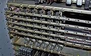
Trunk Link Frame
Junctors were wired from LLF through the Junctor Grouping Frame to the levels of Trunk Junctor Switches in the Trunk Link Frame (TLF). Unlike earlier designs, the junctors had no supervisoryLine signaling
Line signaling is a class of telecommunications signaling protocols. Line signaling is responsible for off-hook, ringing signal, answer, ground start, on-hook unidirectional supervision messaging in each direction from calling party to called party and vice versa...
relays or other active hardware, all such functions being assigned to trunk circuits. The basic design of the TLF had ten Junctor Switches with their horizontal multiples split in half, hence two hundred Junctors, and two hundred Trunk Links to the ten Trunk Switches. The banjo wiring of the Trunk Switch was not split, but a "discriminator level" trick devoted two levels to doubling the use of the other eight, thus allowing each Trunk Switch to connect sixteen trunks to its twenty Trunk Links. This resulted in the TLF having a 0.8:1 Trunk Concentration Ratio (TCR). This degree of deconcentration eventually turned out to provide too few trunk appearances for the variety of trunk types needed. The final 1970s 5XB offices had type C trunk switches with twelve levels, using two for discrimination, leaving a TCR of unity.
The TLF having twice as many links, Junctor Switches and Junctors as the LLF, there were always twice as many LLF as TLF. As first designed, the maximum number was ten TLF and twenty LLF, known as 10x20 and, at first rarely achieved. In the late 1950s, multiple Trunk Junctor switch bays (ETL and SETL) were added to give each TLF access to more Junctors. The first expanded version allowed each office to have 20x40, and in the 1960s the maximum reached 30x60. Development stopped at that point because the four stage layout was becoming progressively less efficient at greater sizes, and because the 1ESS switch
1ESS switch
The Number One Electronic Switching System, the first large-scale Stored Program Control telephone exchange or Electronic Switching System in the Bell System, was introduced in Succasunna, New Jersey, in May 1965. The switching fabric was composed of reed matrixes controlled by wire spring relays...
with eight stages was under development.
A Channel from a line to a trunk consisted of three links of switching fabric: Line Link, Junctor, and Trunk Link. In a 10x20 or larger office, ten Channels, numbered 0 to 9, were available from any line to any trunk. The Line Junctor Switch number and the Trunk Junctor Switch number were the same as the Channel number. Logic in the Marker compared the ten links of each kind to obtain a clear channel. The lack of a channel was called a mismatch and resulted in picking another trunk, or another line, or the use of the ALL where that existed, or giving up and letting the caller try again.
Trunk circuits
As in previous designs, supervision of incoming calls was handled by relay sets known as incoming trunk circuits. Unlike in previous designs, this work was also done in the trunk circuit for outgoing calls, so there were no junctor circuits. Since different outgoing trunks were connected to different places and were used for different calls, their relay sets could be specialized for a particular kind of signalling or call metering (see Automatic Message AccountingAutomatic Message Accounting
Automatic message accounting provides detail billing for telephone calls. When direct distance dialing was introduced in the US, message registers no longer sufficed for dialed telephone calls...
) or other peculiarity. Thus a TSPS trunk could give complete control to an operator, while an E and M signaling
E and M signaling
E&M is a type of supervisory line signaling that uses DC signals on separate leads, called the "E" lead and "M" lead, traditionally used in the telecommunications industry between telephone switches....
trunk could do the kind of signaling required of a private long distance line, while a local outgoing trunk could be simpler.
Thanks to this more complex trunk circuit, outgoing trunks were selected by a quicker and more versatile method than the "sleeve test" previously used. Each trunk circuit provided a ground on a FT lead to indicate idleness. The FT leads for trunks in a particular group were cross connected to a FTC (Frame Test Common) lead for its Trunk Link Frame, to indicate that the TLF had one or more idle trunks in that group. The Route Relay in the Completing Marker connected sensor relays to all the Trunk Link Frames, allowing the Marker to choose a TLF that had an idle trunk and then connect to that trunk through the Trunk Link Connector (TLC) to choose one of those idle trunks. This two step method, along with the mixing of incoming and outgoing traffic, distributed traffic more evenly, thus alleviating the link congestion problems that often arose with earlier methods that restricted a trunk group to one or two outgoing switch frames.
This method was less efficient for coin phones, which needed special signalling. In urban areas, they were served by older exchanges that had separate junctors
Cord circuit
In telecommunication, a cord circuit is a switchboard circuit in which a plug-terminated cord is used to establish connections manually between user lines or between trunks and user lines. A number of cord circuits are furnished as part of the switchboard position equipment. The cords may be...
for coin phones. Where the 5XB was the only exchange, a number of work-around methods were devised. POTS and coin phones shared the more complex and expensive coin trunks, or else separate routes were established, or coin trunks connected via tandems
Class 4 telephone switch
A Class 4, or Tandem, telephone switch is a U.S. telephone company central office telephone exchange used to interconnect local exchange carrier offices for long distance communications in the Public Switched Telephone Network....
including the 5XB itself acting as its own tandem. In this last case, the call had to use two connections through the switching fabric: One to connect the line to the coin supervision trunk and another to connect that trunk to the outgoing trunk.
It was also less efficient for tandem calls, since the fabric was unable to connect a trunk directly to a trunk. Instead each incoming trunk that had the ability to make tandem calls had to have a Line Link Frame appearance, as though it were a line. To avoid expense, incoming trunks were divided into groups, some of them having tandem ability and some not. This complication was avoided in places big enough to pay for a separate tandem switch.
Register signaling
In telecommunications, register signaling provides addressing information, such as the calling and/or called telephone number. R2 register signaling is an example.This is contrasted with line signaling....
and outgoing senders was not through the four stage voice fabric. Rather it was through a dedicated single stage crossbar network known as Incoming Register Link (IRL) or Outgoing Sender Link (OSL) respectively. Registers and senders were in groups of ten, assigned one to each level of as many crossbar switches as were appropriate to the traffic they could handle. Different trunks were wired to different IRL or OSL depending on what kind of signaling they used; ie IRDP, IRRP (See Panel switch
Panel switch
The panel switching system was an early type of automatic telephone exchange, first put into urban service by the Bell System in the 1920s and removed during the 1970s...
), or IRMF
Multi-frequency
In telephony, multi-frequency signaling is an outdated, in-band signaling technique. Numbers were represented in a two-out-of-five code for transmission from a multi-frequency sender, to be received by a multi-frequency receiver in a distant telephone exchange...
.
Previous systems used relays in the incoming trunk circuit to control ringing and to return busy tone. 5XB used a ringing Selection Switch (RSS), a crossbar switch with ten verticals, serving ten trunks. The various levels provided various tones, and ringing current of various durations and cadences (especially valuable for party line
Party line (telephony)
In twentieth-century telephone systems, a party line is an arrangement in which two or more customers are connected directly to the same local loop. Prior to World War II in the United States, party lines were the primary way residential subscribers acquired local telephone service...
s). Levels 0 and 1 were used as discriminating levels to set polarity for selective ringing on tip side or ring side
Tip and ring
"Tip" and "Ring" are common terms in the telephone service industry referring to the two wires or sides of an ordinary telephone line. Tip is the ground side and Ring is the battery side of a phone circuit. In the UK these are referred to as the 'A' and 'B' wires...
. An especially sensitive wire spring RT relay was used to detect off-hook
Off-hook
In telephony, the term off-hook has the following meanings:# The condition that exists when a telephone or other user instrument is in use, i.e., during dialing or communicating. Note: off-hook originally referred to the condition that prevailed when telephones had a separate earpiece , which hung...
from a line being rung, release the RSS hold magnet, and engage the shielded supervision relay so reverse battery answer supervision
Answer supervision
Answer supervision is a term in telephony, describing a situation whereby the called party indicates to the central office that the call is being answered. -CAS E&M Signaling Basics:...
would be returned to the originating end.
Common control
Panel switch
The panel switching system was an early type of automatic telephone exchange, first put into urban service by the Bell System in the 1920s and removed during the 1970s...
.
Originating Registers (OR) were wired to the Trunk Link Frame (TLF). In the original 5XB a marker, having been alerted to a trip condition, picked an OR by the same mechanism it would use to pick a trunk, identified a clear path between line and OR, loaded the OR with any information necessary for later processing (such as Line Equipment and Class of Service) and released itself. The OR then received the digits (rotary or tone), stored them in reed relay packs, and used the Pretranslator to determine how many digits to receive before calling in the Marker again to complete the call.
Larger 5XB were built in the 1960s with more Markers. To save money the markers were separated into two kinds: simple Dial Tone Markers (DTM) just to connect the line to the OR, and Completing Markers (CM), many times more complex and expensive, to complete the call to or from a trunk. CM had, among other features, the ability to translate the first 3 digits of a phone number (or 6 when using a separate Foreign Area Translator) to identify the correct outgoing trunks and handling.
Connectors, similar in purpose to the data buses inside a computer CPU, connected the Markers to the peripheral equipment. Each Connector was made up of large relays of 30 contacts each, to connect all the leads by which the Marker would exchange information and control signals. For example, each of the oblong reed packs in an OR would have to be connected by five leads through the Originating Register Marker Connector, to transmit the two-out-of-five code
Two-out-of-five code
In telecommunication, a two-out-of-five code is an m of n code that provides exactly ten possible combinations, and thus is popular for representing decimal digits using five bits...
representing one dialed digit. For speed, transfer was entirely parallel, requiring many large relays to connect so many wires. Connectors that responded to a peripheral circuit's request for action were named with the name of the requesting circuit and "Marker", as in ORMC or IRMC. Connectors whose use was requested by a Marker were named only for the circuit to which they connected, as in Outsender Connector, Line Link Connector, and Trouble Recorder Connector.
One of the drawbacks of step by step and other early systems is that the preference for choosing trunks or selector links was fixed, and the most preferred links are used more often, with the result that the same faulty hardware would block repeated call attempts until it was removed from service. 5XB markers were designed to rotate preferences in such a way that it was highly unlikely that the same circuit elements would be used in the next call. Thus, if a call encountered an equipment problem, a second try would probably succeed.
Partly because of this deliberate design decision to help shield users from component failures, the few, shared markers contained a great deal of self-checking circuitry. This was feasible because there were only a few markers, and beneficial because their correct function was critical. Digit codes, for instance, were checked to ensure that exactly two out of the five lines were activated. When the built in self test circuits of a marker detected an error, a large punch card was produced at the test station recording the failure in order to assist the switchmen in detecting it and diagnosing the source. The card punch, with some cards, is visible in the lower left of the test frame picture below.
Testing
Centrex
Centrex is a portmanteau of central exchange, a kind of telephone exchange.In the United Kingdom, British Telecom markets this service as FeatureLine .-Use of Centrex:...
, Direct Distance Dialing
Direct distance dialing
Direct distance dialing or direct dial is a telecommunications term for a network-provided service feature in which a call originator may, without operator assistance, call any other user outside the local calling area. DDD requires more digits in the number dialed than are required for calling...
and other innovations brought more complications to the tasks of translation and trunk selection. For lines, MTF could test translations and conduct voltmeter tests to detect impedance imbalances and other electrical conditions that could impair service.
Other test equipment included a Line Insulation Tester and an Automatic Trunk Tester, for items whose numerosity and simplicity lent themselves to automatic testing. An automated AMA translator tester checked for miswiring that could bill one line to another. A non automated Outgoing Trunk test panel allowed voltmeter checks on trunks to distant offices, freeing the MTF from this tedious job. Each Outgoing Trunk was represented by two jacks: one for test access for the voltmeter and one for Make Busy. MTF was able to override Make Busy when necessary.
Advanced services
The first office capable of International Direct Distance Dialing (IDDD) in the United States was the LT-1 exchange on the 10th floor of the 435 West 50th Street exchange building in Manhattan. A group of its MF senders were equipped for the unique dual outpulse requirements of that service. Most large new urban 5XB in subsequent years had IDDD, and it was retrofitted to some existing ones, but most omitted the dual outpulse capability, that job being handled by TSPS.Also taking advantage of the superior versatility of 5XB, Centrex
Centrex
Centrex is a portmanteau of central exchange, a kind of telephone exchange.In the United Kingdom, British Telecom markets this service as FeatureLine .-Use of Centrex:...
was invented as a service package. Later Stored Program Control exchange
Stored Program Control exchange
Stored Program Control exchange is the technical name used for telephone exchanges controlled by a computer program stored in the memory of the system. Early exchanges such as Strowger, panel, rotary, and crossbar switches were electromechanical and had no software control...
s allowed more extensive service features. Autovon
Autovon
AUTOVON, short for Automatic Voice Network, was an American military phone system built in 1963 to survive nuclear attacks. AUTOVON was first established in the United States, using the Army's SCAN system. Around the mid-1970s AUTOVON expanded to the United Kingdom, Asia, the Middle East, and Panama...
originally used a four wire version of 5XB, with a more complex marker
Marker (telecommunications)
A marker is a type of special purpose control system that was used in electromechanical telephone central office switches. Central office switches are the large devices that telephone companies use to make the connections that support telephone calls...
to implement its nonhierarchical Polygrid routing system, and trunk circuits with additional logic and data storage built in to implement preemption.
Picturephone arrived in the early 1970s. 1ESS switch
1ESS switch
The Number One Electronic Switching System, the first large-scale Stored Program Control telephone exchange or Electronic Switching System in the Bell System, was introduced in Succasunna, New Jersey, in May 1965. The switching fabric was composed of reed matrixes controlled by wire spring relays...
was already going into service and provided a more sophisticated basis for advanced services, but was not yet as widely available, so 5XB was designated as the switching vehicle. Every Picturephone line had six wires: the old talking pair plus a video transmit pair and a video receive pair. A new wideband switching fabric was designed using a 6 wire version of Type B crossbar switches, two of the wires being grounded, thus diminishing crosstalk for the two video pairs. When completing a Picturephone call, the Completing Marker first picked the line or trunk to which the audio portion of the call would be completed, and then set up both the audio switches and the video ones. Wideband Remote Switches (WBRS) were installed in smaller exchanges, as video concentrators for lines that were beyond video range from a larger exchange that had been given the Picturephone feature.