

Intel 8255
Encyclopedia
Peripheral
A peripheral is a device attached to a host computer, but not part of it, and is more or less dependent on the host. It expands the host's capabilities, but does not form part of the core computer architecture....
Interface
Interface (computer science)
In the field of computer science, an interface is a tool and concept that refers to a point of interaction between components, and is applicable at the level of both hardware and software...
chip is a peripheral chip originally developed for the Intel 8085
Intel 8085
The Intel 8085 is an 8-bit microprocessor introduced by Intel in 1977. It was binary-compatible with the more-famous Intel 8080 but required less supporting hardware, thus allowing simpler and less expensive microcomputer systems to be built....
microprocessor, and as such is a member of a large array of such chips, known as the MCS-85 Family. This chip was later also used with the Intel 8086
Intel 8086
The 8086 is a 16-bit microprocessor chip designed by Intel between early 1976 and mid-1978, when it was released. The 8086 gave rise to the x86 architecture of Intel's future processors...
and its descendants.
It was later made (cloned) by many other manufacturers. It is made in DIP
Dual in-line package
In microelectronics, a dual in-line package is an electronic device package with a rectangular housing and two parallel rows of electrical connecting pins. The package may be through-hole mounted to a printed circuit board or inserted in a socket.A DIP is usually referred to as a DIPn, where n is...
40 and PLCC
Plastic leaded chip carrier
A plastic leaded chip carrier is a chip carrier with a equiangular plastic housing. It is a reduced cost evolution of the ceramic leadless chip carrier ....
44 pins encapsulated versions.
Similar chips
This chip is used to give the CPU access to programmable parallel I/OInput/output
In computing, input/output, or I/O, refers to the communication between an information processing system , and the outside world, possibly a human, or another information processing system. Inputs are the signals or data received by the system, and outputs are the signals or data sent from it...
, and is similar to other such chips like the Motorola 6520 PIA
Peripheral Interface Adapter
The Peripheral Interface Adapter is a peripheral integrated circuit providing parallel I/O interfacing capability for microprocessor systems. Common PIAs include the Motorola MC6820 and MC6821, and the MOS Technology MCS6520, all of which are functionally identical but have slightly different...
(Peripheral Interface Adapter) the MOS Technology 6522
MOS Technology 6522
The 6522 Versatile Interface Adapter was an integrated circuit made by MOS Technology, as well as second sources including Rockwell and Synertek. It served as a I/O port controller for the 6502 family of microprocessors, providing the parallel I/O capabilities of the PIA as well as timers and a...
(Versatile Interface Adapter) and the MOS Technology CIA
MOS Technology CIA
The 6526/8520 Complex Interface Adapter was an integrated circuit made by MOS Technology. It served as a I/O port controller for the 6502 family of microprocessors, providing for parallel and serial I/O capabilities as well as timers and a Time-of-Day clock...
(Complex Interface Adapter) all developed for the 6502
MOS Technology 6502
The MOS Technology 6502 is an 8-bit microprocessor that was designed by Chuck Peddle and Bill Mensch for MOS Technology in 1975. When it was introduced, it was the least expensive full-featured microprocessor on the market by a considerable margin, costing less than one-sixth the price of...
family. Other such chips are the 2655 Programmable Peripheral Interface from the Signetics 2650
Signetics 2650
The Signetics 2650, was a very early 8-bit microprocessor. According to Adam Osborne's classic book An Introduction to Microprocessors Vol 2: Some Real Products, it was "the most minicomputer-like" of the microprocessors available at the time....
family of microprocessors, the 6820 PIO (Peripheral Input/Output) from the Motorola 6800
Motorola 6800
The 6800 was an 8-bit microprocessor designed and first manufactured by Motorola in 1974. The MC6800 microprocessor was part of the M6800 Microcomputer System that also included serial and parallel interface ICs, RAM, ROM and other support chips...
family, the Western Design Center
Western Design Center
The Western Design Center , located in Mesa, Arizona, USA, is a company developing and manufacturing MOS 65xx-based microprocessors, microcontrollers , and related support chips...
WDC 65C21
WDC 65C21
The W65C21S is a very flexible Peripheral Interface Adapter for use with WDC’s 65xx and other 8-bit microprocessor families. It is produced by Western Design Center ....
, an enhanced 6520, and many others.
However, most often the functionality 8255 offered is now not implemented with the 8255 chip itself anymore, but is embedded in a larger VLSI
Very-large-scale integration
Very-large-scale integration is the process of creating integrated circuits by combining thousands of transistors into a single chip. VLSI began in the 1970s when complex semiconductor and communication technologies were being developed. The microprocessor is a VLSI device.The first semiconductor...
chip as a sub function. The 8255 chip itself is still made, and is sometimes used together with a micro controller to expand its I/O capabilities.
Computers that had used the chip
The 8255 is widely used not only in many microcomputer/microcontroller systems especially Z-80 based, home computerHome computer
Home computers were a class of microcomputers entering the market in 1977, and becoming increasingly common during the 1980s. They were marketed to consumers as affordable and accessible computers that, for the first time, were intended for the use of a single nontechnical user...
s such as SV-328
SV-328
The SV-328 is an 8-bit home computer introduced by Spectravideo in June 1983. It was the business-targeted model of the Spectravideo range, sporting a rather crowded full-travel keyboard with numeric keypad. It had 80 kB RAM , a respectable amount for its time...
and all MSX
MSX
MSX was the name of a standardized home computer architecture in the 1980s conceived by Kazuhiko Nishi, then Vice-president at Microsoft Japan and Director at ASCII Corporation...
, but also in the system board of the best known original IBM-PC, PC/XT, PC/jr, etc. and clones, along with numerous homebuilt computer
Homebuilt computer
A homebuilt computer is a computer assembled from available components, usually commercial off-the-shelf components, rather than purchased as a complete system from a computer system supplier.- History :...
computers such as the N8VEM
N8VEM
N8VEM is a homebrew computing project. It features a variety of free and open hardware and software. N8VEM builders make their own homebrew computer systems for themselves and share their experiences with other homebrew computer hobbyists...
.
Functional block of 8255
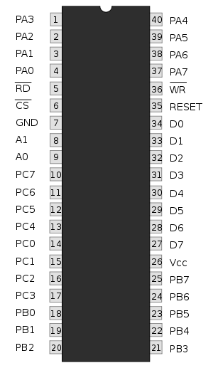
The 8255 has 24 input/output pins in all. These are divided into three 8-bit ports. Port A and port B can be used as 8-bit input/output ports. Port C can be used as an 8-bit input/output port or as two 4-bit input/output ports or to produce handshake signals for ports A and B.The three ports are further grouped as follows:
Eight data lines (D0 - D7) are available (with an 8-bit data buffer) to read/write data into the ports or control register under the status of the "
 RD" (pin 5) and
  WR" (pin 36), which are active low signals for read and write operations respectively. The address lines A1 and A0 allow to successively access any one of the ports or the control register as listed below:
| A1 | A0 | Function |
|---|---|---|
| 0 | 0 | port A |
| 0 | 1 | port B |
| 1 | 0 | port C |
| 1 | 1 | control register |
The control signal "
 CS" (pin 6) is used to enable the 8255 chip. It is an active low signal, i.e., when
  CS = '0' , the 8255 is enabled. The RESET input (pin 35) is connected to a system (like 8085, 8086, etc. ) reset line so that when the system is reset, all the ports are initialised as input lines. This is done to prevent 8255 and/or any peripheral connected to it, from being destroyed due to mismatch of ports. This is explained as follows. Suppose an input device is connected to 8255 at port A. If from the previous operation, port A is initialised as an output port and if 8255 is not reset before using the current configuration, then there is a possibility of damage of either the input device connected or 8255 or both since both 8255 and the device connected will be sending out data.
The control register or the control logic or the command word register is an 8-bit register used to select the modes of operation and input/output designation of the ports.
Input/output mode
There are three types of the input/output mode which are as follows:Mode 0
In this mode, the ports can be used for simple input/output operations without handshaking. If both port A and B are initialized in mode 0, the two halves of port C can be either used together as an additional 8-bit port, or they can be used as individual 4-bit ports. Since the two halves of port C are independent, they may be used such that one-half is initialized as an input port while the other half is initialized as an output port.
The input/output features in mode 0 are as follows:
Mode 1
When we wish to use port A or port B for handshake (strobed) input or output operation, we initialise that port in mode 1 (port A and port B can be initilalised to operate in different modes, i.e., for e.g., port A can operate in mode 0 and port B in mode 1). Some of the pins of port C function as handshake lines.
For port B in this mode (irrespective of whether is acting as an input port or output port), PC0, PC1 and PC2 pins function as handshake lines.
If port A is initialised as mode 1 input port, then, PC3, PC4 and PC5 function as handshake signals. Pins PC6 and PC7 are available for use as input/output lines.
The mode 1 which supports handshaking has following features:
Mode 2
Only group A can be initialised in this mode. Port A can be used for bidirectional handshake data transfer. This means that data can be input or output on the same eight lines (PA0 - PA7). Pins PC3 - PC7 are used as handshake lines for port A. The remaining pins of port C (PC0 - PC2) can be used as input/output lines if group B is initialised in mode 0. In this mode, the 8255 may be used to extend the system bus to a slave microprocessor
Microprocessor
A microprocessor incorporates the functions of a computer's central processing unit on a single integrated circuit, or at most a few integrated circuits. It is a multipurpose, programmable device that accepts digital data as input, processes it according to instructions stored in its memory, and...
or to transfer data bytes to and from a floppy disk
Floppy disk
A floppy disk is a disk storage medium composed of a disk of thin and flexible magnetic storage medium, sealed in a rectangular plastic carrier lined with fabric that removes dust particles...
controller.
Bit set/reset (BSR) mode
In this mode only port B can be used (as an output port). Each line of port C (PC0 - PC7) can be set/reset by suitably loading the command word register.no effect occurs in input-output mode.The individual bits of port c can be set or reset by sending the signal OUT instruction to the control register.
Input/output mode format
- The figure shows the control word format in the input/output mode. This mode is selected by making D7 = '1' .
- D0, D1, D3, D4 are for lower port C, port B, upper port C and port A respectively. When D0 or D1 or D3 or D4 are "SET", the corresponding ports act as input ports. For e.g., if D0 = D4 = '1', then lower port C and port A act as input ports. If these bits are "RESET", then the corresponding ports act as output ports. For e.g., if D1 = D3 = '0', then port B and upper port C act as output ports.
- D2 is used for mode selection for group B (Port B and Lower Port C). When D2 = '0', mode 0 is selected and when D2 = '1', mode 1 is selected.
- D5, D6 are used for mode selection for group A (Upper Port C and Port A). The format is as follows:
| D6 | D5 | mode |
|---|---|---|
| 0 | 0 | 0 |
| 0 | 1 | 1 |
| 1 | x | 2 |
Example:
If port B and upper port C have to be initialised as input ports and lower port C and port A as ouput ports (all in mode 0), what is the control word?
-
- 1. Since it is an input/ouput mode, D7 = '1'.
- 2. Mode selection bits, D2, D5, D6 are all '0' for mode 0 operation.
- 3. Port B should operate as input port, hence, D1 = '1'.
- 4. Upper port C should also be an input port, hence, D3 = '1'.
- 5. Port A has to operate output port, hence, D4 = '0'.
- 6. Lower port C should also operate as output port, hence, D0 = '0'.
Applying the corresponding values to the format in input/output mode, we get the control word as "8A (hex)"
BSR mode format
- The figure shows the control word format in BSR mode. This mode is selected by making D7='0'.
- D0 is used for bit set/reset. When D0= '1', the port C bit selected (selection of a port C bit is shown in the next point) is SET, when D0 = '0', the port C bit is RESET.
- D1, D2, D3 are used to select a particular port C bit whose value may be altered using D0 bit as mentioned above. The selection of the port C bits are done as follows:
| D3 | D2 | D1 | Bit/pin of port C selected |
|---|---|---|---|
| 0 | 0 | 0 | PC0 |
| 0 | 0 | 1 | PC1 |
| 0 | 1 | 0 | PC2 |
| 0 | 1 | 1 | PC3 |
| 1 | 0 | 0 | PC4 |
| 1 | 0 | 1 | PC5 |
| 1 | 1 | 0 | PC6 |
| 1 | 1 | 1 | PC7 |
- D4, D5, D6 are not used.
Example:
If the 5th bit (PC5) of port C has to be "SET", then what is the control word?
-
- 1. Since it is BSR mode, D7 = '0'.
- 2. Since D4, D5, D6 are not used, assume them to be '0'.
- 3. PC5 has to be selected, hence, D3 = '1', D2 = '0', D1 = '1'.
- 4. PC5 has to be set, hence, D0 = '1'.
Applying the above values to the format for BSR mode, we get the control word as "0B (hex)".
External links
- Complete Description about the Intel 8255 IC
- 8255 Datasheet (PDF)
- http://www.sharpmz.org/mz-700/8255ovview.htm