

Flyback converter
Encyclopedia
The flyback converter is used in both AC/DC and DC/DC conversion with galvanic isolation
between the input and any outputs. More precisely, the flyback converter is a buck-boost converter
with the inductor split to form a transformer, so that the voltage ratios are multiplied with an additional advantage of isolation. When driving for example a plasma lamp or a voltage multiplier
the rectifying diode
of the buck-boost converter is left out and the device is called a flyback transformer
.
 The schematic of a flyback converter can be seen in figure 1. It is equivalent to that of a buck-boost converter
, with the inductor split to form a transformer . Therefore the operating principle of both converters is very close:
 The flyback converter is an isolated power converter, therefore the isolation of the control circuit is also needed. The two prevailing control schemes are voltage mode control and current mode control (In the majority of cases current mode control needs to be dominant for stability during operation). Both require a signal related to the output voltage. There are two common ways to generate this voltage. The first is to use an optocoupler on the secondary circuitry to send a signal to the controller. The second is to wind a separate winding on the coil and rely on the cross regulation of the design.
The first technique involving an optocoupler has been used to obtain tight voltage and current regulation; whereas the alternative approach was developed for cost-sensitive applications where the output did not need to be as tightly controlled but up to 11 components including the optocoupler could be eliminated from the overall design. Also in applications where reliability is critical, optocouplers can be detrimental to the MTBF (Mean Time Between Failure) calculations.
Recent developments in primary-side sensing technology, where the output voltage and current are regulated by monitoring the waveforms in the auxiliary winding used to power the control IC itself, have improved the accuracy of both voltage and current regulation.
Previously a measurement was taken across the whole of the flyback waveform which led to error, but it was realized that measurements at the so-called knee point (when the secondary current is zero, see waveform trace) allow for a much more accurate measurement of what is happening on the secondary side. This topology is now replacing ringing choke converter (RCC) in applications such as mobile phone chargers.
Continuous mode has the following disadvantages, which complicate the control of the converter:
Galvanic isolation
Galvanic isolation is a principle of isolating functional sections of electrical systems, thus preventing the movement of charge-carrying particles from one section to another, i.e. no direct current flows between the sections. Energy or information can still be exchanged between the sections by...
between the input and any outputs. More precisely, the flyback converter is a buck-boost converter
Buck-boost converter
The buck–boost converter is a type of DC-to-DC converter that has an output voltage magnitude that is either greater than or less than the input voltage magnitude.Two different topologies are called buck–boost converter....
with the inductor split to form a transformer, so that the voltage ratios are multiplied with an additional advantage of isolation. When driving for example a plasma lamp or a voltage multiplier
Voltage multiplier
thumb|right|280px|Villard cascade voltage multiplier.A voltage multiplier is an electrical circuit that converts AC electrical power from a lower voltage to a higher DC voltage, typically by means of a network of capacitors and diodes....
the rectifying diode
Diode
In electronics, a diode is a type of two-terminal electronic component with a nonlinear current–voltage characteristic. A semiconductor diode, the most common type today, is a crystalline piece of semiconductor material connected to two electrical terminals...
of the buck-boost converter is left out and the device is called a flyback transformer
Flyback transformer
A flyback transformer , also called a line output transformer , is a special transformer, which is used for conversion of energy in electronic circuits. It was initially designed to generate high current sawtooth signals at a relatively high frequency...
.
Structure and principle
Buck-boost converter
The buck–boost converter is a type of DC-to-DC converter that has an output voltage magnitude that is either greater than or less than the input voltage magnitude.Two different topologies are called buck–boost converter....
, with the inductor split to form a transformer . Therefore the operating principle of both converters is very close:
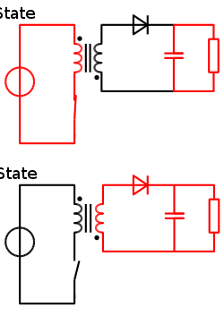
- When the switch is on (see figure 2), the primary of the transformer is directly connected to the input voltage source. This results in an increase of magnetic flux in the transformer. The voltage across the secondary winding is negative, so the diode is reverse-biased (i.e., blocked). The output capacitor supplies energy to the output load.
- When the switch is off, the energy stored in the transformer is transferred to the output of the converter.
- The operation of storing energy in the transformer before transferring to the output of the converter allows the topology to easily generate multiple outputs with little additional circuitry, although the output voltages have to be able to match each other through the turns ratio. Also there is a need for a controlling rail which has to be loaded before load is applied to the uncontrolled rails, this is to allow the PWMPulse-width modulationPulse-width modulation , or pulse-duration modulation , is a commonly used technique for controlling power to inertial electrical devices, made practical by modern electronic power switches....
to open up and supply enough energy to the transformer.
Operation
The first technique involving an optocoupler has been used to obtain tight voltage and current regulation; whereas the alternative approach was developed for cost-sensitive applications where the output did not need to be as tightly controlled but up to 11 components including the optocoupler could be eliminated from the overall design. Also in applications where reliability is critical, optocouplers can be detrimental to the MTBF (Mean Time Between Failure) calculations.
Recent developments in primary-side sensing technology, where the output voltage and current are regulated by monitoring the waveforms in the auxiliary winding used to power the control IC itself, have improved the accuracy of both voltage and current regulation.
Previously a measurement was taken across the whole of the flyback waveform which led to error, but it was realized that measurements at the so-called knee point (when the secondary current is zero, see waveform trace) allow for a much more accurate measurement of what is happening on the secondary side. This topology is now replacing ringing choke converter (RCC) in applications such as mobile phone chargers.
Limitations
Discontinuous mode has the following disadvantages, which limit the efficiency of the converter:- High RMS and peak currents in the design
- High flux excursions in the inductor
Continuous mode has the following disadvantages, which complicate the control of the converter:
- The voltage feedback loop requires a lower bandwidth due to a zero in the response of the converter.
- The current feedback loop used in current mode control needs slope compensation in cases where the duty cycleDuty cycleIn engineering, the duty cycle of a machine or system is the time that it spends in an active state as a fraction of the total time under consideration....
is above 50%. - The power switches are now turning on with positive current flow - this means that in addition to turn-off speed, the switch turn-on speed is also important for efficiency and reducing waste heat in the switching element.
Applications
- Low-power switch-mode power supplies (cell phone charger, standby power supply in PCs)
- Low cost multiple-output power supplies (e.g., main PC supplies <250 W)
- High voltage supply for the CRTCathode ray tubeThe cathode ray tube is a vacuum tube containing an electron gun and a fluorescent screen used to view images. It has a means to accelerate and deflect the electron beam onto the fluorescent screen to create the images. The image may represent electrical waveforms , pictures , radar targets and...
in TVs and monitors (the flyback converter is often combined with the horizontal deflection drive). - High voltage generation (e.g., for xenon flash lamps, lasers, copiers, etc).
- Isolated gate driver.