

Current divider rule
Encyclopedia

Electronics
Electronics is the branch of science, engineering and technology that deals with electrical circuits involving active electrical components such as vacuum tubes, transistors, diodes and integrated circuits, and associated passive interconnection technologies...
, a current divider is a simple linear circuit
Linear circuit
A linear circuit is an electronic circuit in which, for a sinusoidal input voltage of frequency f, any output of the circuit is also sinusoidal with frequency f...
that produces an output current
Electric current
Electric current is a flow of electric charge through a medium.This charge is typically carried by moving electrons in a conductor such as wire...
(IX) that is a fraction of its input current (IT). Current division refers to the splitting of current between the branches of the divider. The currents in the various branches of such a circuit will always divide in such a way as to minimize the total energy expended.
The formula describing a current divider is similar in form to that for the voltage divider. However, the ratio describing current division places the impedance of the unconsidered branches in the numerator, unlike voltage division where the considered impedance is in the numerator. This is because in current dividers, total energy expended is minimized, resulting in currents that go through paths of least impedance, therefore the inverse relationship with impedance. On the other hand, voltage divider is used to satisfy Kirchoff's Voltage Law. The voltage around a loop must sum up to zero, so the voltage drops must be divided evenly in a direct relationship with the impedance.
To be specific, if two or more impedance
Electrical impedance
Electrical impedance, or simply impedance, is the measure of the opposition that an electrical circuit presents to the passage of a current when a voltage is applied. In quantitative terms, it is the complex ratio of the voltage to the current in an alternating current circuit...
s are in parallel, the current that enters the combination will be split between them in inverse proportion to their impedances (according to Ohm's law
Ohm's law
Ohm's law states that the current through a conductor between two points is directly proportional to the potential difference across the two points...
). It also follows that if the impedances have the same value the current is split equally.
Resistive divider
A general formula for the current IX in a resistor RX that is in parallel with a combination of other resistors of total resistance RT is (see Figure 1):
where IT is the total current entering the combined network of RX in parallel with RT. Notice that when RT is composed of a parallel combination of resistors, say R1, R2, ... etc., then the reciprocal of each resistor must be added to find the total resistance RT:

General case
Although the resistive divider is most common, the current divider may be made of frequency dependent impedanceElectrical impedance
Electrical impedance, or simply impedance, is the measure of the opposition that an electrical circuit presents to the passage of a current when a voltage is applied. In quantitative terms, it is the complex ratio of the voltage to the current in an alternating current circuit...
s. In the general case the current IX is given by:
Using Admittance
Instead of using impedanceElectrical impedance
Electrical impedance, or simply impedance, is the measure of the opposition that an electrical circuit presents to the passage of a current when a voltage is applied. In quantitative terms, it is the complex ratio of the voltage to the current in an alternating current circuit...
s, the current divider rule can be applied just like the voltage divider rule if admittance
Admittance
In electrical engineering, the admittance is a measure of how easily a circuit or device will allow a current to flow. It is defined as the inverse of the impedance . The SI unit of admittance is the siemens...
(the inverse of impedance) is used.
Take care to note that YTotal is a straightforward addition, not the sum of the inverses inverted (as you would do for a standard parallel resistive network). For Figure 1, the current IX would be

Example: RC combination
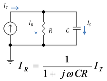
Capacitor
A capacitor is a passive two-terminal electrical component used to store energy in an electric field. The forms of practical capacitors vary widely, but all contain at least two electrical conductors separated by a dielectric ; for example, one common construction consists of metal foils separated...
and a resistor. Using the formula above, the current in the resistor is given by:


where ZC = 1/(jωC) is the impedance of the capacitor.
The product τ = CR is known as the time constant
Time constant
In physics and engineering, the time constant, usually denoted by the Greek letter \tau , is the risetime characterizing the response to a time-varying input of a first-order, linear time-invariant system.Concretely, a first-order LTI system is a system that can be modeled by a single first order...
of the circuit, and the frequency for which ωCR = 1 is called the corner frequency of the circuit. Because the capacitor has zero impedance at high frequencies and infinite impedance at low frequencies, the current in the resistor remains at its DC value IT for frequencies up to the corner frequency, whereupon it drops toward zero for higher frequencies as the capacitor effectively short-circuits the resistor. In other words, the current divider is a low pass filter for current in the resistor.
Loading effect

Figure 3 shows a current amplifier example. The amplifier (gray box) has input resistance Rin and output resistance Rout and an ideal current gain Ai. With an ideal current driver (infinite Norton resistance) all the source current iS becomes input current to the amplifier. However, for a Norton driver
Norton's theorem
Norton's theorem for linear electrical networks, known in Europe as the Mayer–Norton theorem, states that any collection of voltage sources, current sources, and resistors with two terminals is electrically equivalent to an ideal current source, I, in parallel with a single resistor, R...
a current divider is formed at the input that reduces the input current to
which clearly is less than iS. Likewise, for a short circuit at the output, the amplifier delivers an output current io = Ai ii to the short-circuit. However, when the load is a non-zero resistor RL, the current delivered to the load is reduced by current division to the value:
Combining these results, the ideal current gain Ai realized with an ideal driver and a short-circuit load is reduced to the loaded gain Aloaded:

The resistor ratios in the above expression are called the loading factors. For more discussion of loading in other amplifier types, see loading effect.
Unilateral versus bilateral amplifiers

Two-port network
A two-port network is an electrical circuit or device with two pairs of terminals connected together internally by an electrical network...
, the input resistance of the amplifier depends on its load, and the output resistance on the source impedance. The loading factors in these cases must employ the true amplifier impedances including these bilateral effects. For example, taking the unilateral current amplifier of Figure 3, the corresponding bilateral two-port network is shown in Figure 4 based upon h-parameters. Carrying out the analysis for this circuit, the current gain with feedback Afb is found to be
That is, the ideal current gain Ai is reduced not only by the loading factors, but due to the bilateral nature of the two-port by an additional factor ( 1 + β (RL / RS ) Aloaded ), which is typical of negative feedback amplifier circuits. The factor β (RL / RS ) is the current feedback provided by the voltage feedback source of voltage gain β V/V. For instance, for an ideal current source with RS = ∞ Ω, the voltage feedback has no influence, and for RL = 0 Ω, there is zero load voltage, again disabling the feedback.
See also
- Voltage divider
- ResistorResistorA linear resistor is a linear, passive two-terminal electrical component that implements electrical resistance as a circuit element.The current through a resistor is in direct proportion to the voltage across the resistor's terminals. Thus, the ratio of the voltage applied across a resistor's...
- Ohm's lawOhm's lawOhm's law states that the current through a conductor between two points is directly proportional to the potential difference across the two points...
- Thevenin's theoremThévenin's theoremIn circuit theory, Thévenin's theorem for linear electrical networks states that any combination of voltage sources, current sources, and resistors with two terminals is electrically equivalent to a single voltage source V and a single series resistor R. For single frequency AC systems the theorem...
- Voltage regulationVoltage regulationIn electrical engineering, particularly power engineering, voltage regulation is the ability of a system to provide near constant voltage over a wide range of load conditions.-Electrical power systems:...