
Caltech Intermediate Form
Encyclopedia
Caltech Intermediate Form (CIF) is a file format
for describing integrated circuit
s.
CIF provides a limited set of graphics primitives that are useful for describing the two-dimensional
shapes on the different layers of a chip.
The format allows hierarchical description, which makes the representation concise.
In addition, it is a terse but human-readable
text format.
with a semicolon.
Spaces must separate the parameters but there are no restrictions on the number of statements
per line or of the particular columns of any field.
Comments can be inserted anywhere by enclosing them in parenthesis.
There are only a few CIF statements and they fall into one of two categories: geometry or control.
The geometry statements are:
rectangle,
figure, and
The control statements are
definition of a subroutine,
include additional user-specified information, and
All of these keywords are usually abbreviated to one or two letters that are unique.
for all subsequent geometry until the next such statement.
Following the
For example, the command:
L CC;
sets the layer to be the CMOS contact cut (see Fig. B.1 for some typical MOS layer names).
The
specifying geometry.
It describes a rectangle by giving its length, width, center position, and an optional rotation.
The format is as follows:
B length width xpos ypos [rotation] ;
Without the rotation field, the four numbers specify a box the center of which is
at (xpos, ypos) and is length across in x and width tall in y.
All numbers in CIF are integers that refer to centimicrons of distance, unless subroutine
scaling is specified (described later).
The optional rotation field contains two numbers that define a vector endpoint
starting at the origin.
The default value of this field is (1, 0), which is a right-pointing vector.
Thus the rotation clause
Similarly,
Note that the magnitude of this rotation vector has no meaning.
 The
The
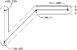
path that runs between a set of points.
The path can have a nonzero width and has rounded corners.
After the
number of coordinate pairs that describe the endpoints.
Figure B.2 shows a sample wire.
Note that the endpoint and corner rounding are implicitly handled.
The
circle, given the diameter and the center coordinate. For example, the statement:
R 20 30 40;
will draw a circle that has a radius of 10 (diameter of 20), centered at (30, 40).
 The
The
coordinate pairs and draws a filled polygon from them.
Since filled polygons must be closed, the first and last coordinate points are
implicitly connected and need not be the same.
Polygons can be arbitrarily complex, including concavity and self-intersection.
Figure B.3 illustrates a polygon statement.
of other statements that have been packaged with
All subroutines are given numbers when they are defined and these numbers are used in
the
If, for example, a
packaged into subroutine 4, then the statement:
C 4;
will cause the box to be drawn on that layer.
In addition to simply invoking the subroutine, a
transformations to affect the geometry inside the subroutine.
Three transformations can be applied to a subroutine in CIF: translation, rotation, and mirroring.
Translation is specified as the letter
These offsets will be added to all coordinates in the subroutine, to translate its
graphics across the mask.
Rotation is specified as the letter
that, much like the rotation clause in the
The unrotated line has the endpoint (1, 0), which points to the right.
Mirroring is available in two forms:
Mirroring is a bit confusing, because
coordinate, which effectively mirrors about the y axis.
 Any number of transformations can be applied to an object and their listed order
is the sequence that will be used to apply them.
Figure B.4 shows some examples, illustrating the importance of ordering the
transformations (notice that Figs. B.4c and B.4d produce different results by
rearranging the transformations).
Defining subroutines for use in a
The statements to be packaged are enclosed between
start) and
Arguments to the
There are no arguments to the
The scaling factor for a subroutine consists of a numerator followed by a denominator
that will be applied to all values inside the subroutine.
This scaling allows large numbers to be expressed with fewer digits and allows ease
of rescaling a design.
The scale factor cannot be changed for each invocation of the subroutine since it
is applied to the definition.
As an example, the subroutine of Fig. B.4 can be described formally as follows:
DS 10 20 2;
B10 20 5 5;
W1 5 5 10 15;
DF;
Note that the scale factor is 20/2, which allows the trailing zero to be dropped
from all values inside the subroutine.
Arbitrary depth of hierarchy is allowed in CIF subroutines.
Forward references are allowed provided that a subroutine is defined before it is used.
Thus the sequence:
DS 10;
...
C 11;
DF;
DS 11;
...
DF;
C 10;
is legal, but the sequence:
C 11;
DS 11;
...
DF;
is not. This is because the actual invocation of subroutine 11 does
not occur until after its definition in the first example.
The
deletes every subroutine that has a number greater than or equal to this value.
The statement is useful when merging multiple CIF files because designs can be
defined, invoked, and deleted without causing naming conflicts.
However, it is not recommended for general use by CAD systems.
Extensions to CIF can be done with the numeric statements
Although not officially part of CIF, certain conventions have evolved for the
use of these extensions (see Fig. B.5).
The final statement in a CIF file is the
It takes no parameters and typically does not include a semicolon.
File format
A file format is a particular way that information is encoded for storage in a computer file.Since a disk drive, or indeed any computer storage, can store only bits, the computer must have some way of converting information to 0s and 1s and vice-versa. There are different kinds of formats for...
for describing integrated circuit
Integrated circuit
An integrated circuit or monolithic integrated circuit is an electronic circuit manufactured by the patterned diffusion of trace elements into the surface of a thin substrate of semiconductor material...
s.
CIF provides a limited set of graphics primitives that are useful for describing the two-dimensional
shapes on the different layers of a chip.
The format allows hierarchical description, which makes the representation concise.
In addition, it is a terse but human-readable
Human-readable
A human-readable medium or human-readable format is a representation of data or information that can be naturally read by humans.In computing, human-readable data is often encoded as ASCII or Unicode text, rather than presented in a binary representation...
text format.
Overview
Each statement in CIF consists of a keyword or letter followed by parameters and terminatedwith a semicolon.
Spaces must separate the parameters but there are no restrictions on the number of statements
per line or of the particular columns of any field.
Comments can be inserted anywhere by enclosing them in parenthesis.
There are only a few CIF statements and they fall into one of two categories: geometry or control.
The geometry statements are:
LAYER to switch mask layers, BOX to draw arectangle,
WIRE to draw a path, ROUNDFLASH to draw a circle, POLYGON to draw an arbitraryfigure, and
CALL to draw a subroutine of other geometry statements.The control statements are
DS to start the definition of a subroutine, DF to finish thedefinition of a subroutine,
DD to delete the definition of subroutines, 0 through 9 toinclude additional user-specified information, and
END to terminate a CIF file.All of these keywords are usually abbreviated to one or two letters that are unique.
Geometry
TheLAYER statement (or the letter L) sets the mask layer to be usedfor all subsequent geometry until the next such statement.
Following the
LAYER keyword comes a single layer-name parameter.For example, the command:
L CC;
sets the layer to be the CMOS contact cut (see Fig. B.1 for some typical MOS layer names).
| ||||||||||||||||||||||||||||||||||
| FIGURE B.1 CIF layer names for MOS processes. | ||||||||||||||||||||||||||||||||||
The
BOX statement (or the letter B) is the most commonly used way ofspecifying geometry.
It describes a rectangle by giving its length, width, center position, and an optional rotation.
The format is as follows:
B length width xpos ypos [rotation] ;
Without the rotation field, the four numbers specify a box the center of which is
at (xpos, ypos) and is length across in x and width tall in y.
All numbers in CIF are integers that refer to centimicrons of distance, unless subroutine
scaling is specified (described later).
The optional rotation field contains two numbers that define a vector endpoint
starting at the origin.
The default value of this field is (1, 0), which is a right-pointing vector.
Thus the rotation clause
10 5 defines a 30-degree counterclockwise rotation from the normal.Similarly,
10 -10 will rotate clockwise by 45 degrees.Note that the magnitude of this rotation vector has no meaning.
WIRE statement (or the letter W) is used to construct apath that runs between a set of points.
The path can have a nonzero width and has rounded corners.
After the
WIRE keyword comes the width value and then an arbitrarynumber of coordinate pairs that describe the endpoints.
Figure B.2 shows a sample wire.
Note that the endpoint and corner rounding are implicitly handled.
The
ROUNDFLASH statement (or the letter R) draws a filledcircle, given the diameter and the center coordinate. For example, the statement:
R 20 30 40;
will draw a circle that has a radius of 10 (diameter of 20), centered at (30, 40).
POLYGON statement (or the letter P) takes a series ofcoordinate pairs and draws a filled polygon from them.
Since filled polygons must be closed, the first and last coordinate points are
implicitly connected and need not be the same.
Polygons can be arbitrarily complex, including concavity and self-intersection.
Figure B.3 illustrates a polygon statement.
Hierarchy
TheCALL statement (or the letter C) invokes a collectionof other statements that have been packaged with
DS and DF.All subroutines are given numbers when they are defined and these numbers are used in
the
CALL to identify them.If, for example, a
LAYER statement and a BOX statement arepackaged into subroutine 4, then the statement:
C 4;
will cause the box to be drawn on that layer.
In addition to simply invoking the subroutine, a
CALL statement can includetransformations to affect the geometry inside the subroutine.
Three transformations can be applied to a subroutine in CIF: translation, rotation, and mirroring.
Translation is specified as the letter
T followed by an x, y offset.These offsets will be added to all coordinates in the subroutine, to translate its
graphics across the mask.
Rotation is specified as the letter
R followed by an x, y vector endpointthat, much like the rotation clause in the
BOX statement, defines a line to the origin.The unrotated line has the endpoint (1, 0), which points to the right.
Mirroring is available in two forms:
MX to mirror in x and MY to mirror in y.Mirroring is a bit confusing, because
MX causes a negation of the xcoordinate, which effectively mirrors about the y axis.
is the sequence that will be used to apply them.
Figure B.4 shows some examples, illustrating the importance of ordering the
transformations (notice that Figs. B.4c and B.4d produce different results by
rearranging the transformations).
Defining subroutines for use in a
CALL statement is quite simple.The statements to be packaged are enclosed between
DS (definitionstart) and
DF (definition finish) statements.Arguments to the
DS statement are the subroutine number and a subroutine scaling factor.There are no arguments to the
DF statement.The scaling factor for a subroutine consists of a numerator followed by a denominator
that will be applied to all values inside the subroutine.
This scaling allows large numbers to be expressed with fewer digits and allows ease
of rescaling a design.
The scale factor cannot be changed for each invocation of the subroutine since it
is applied to the definition.
As an example, the subroutine of Fig. B.4 can be described formally as follows:
DS 10 20 2;
B10 20 5 5;
W1 5 5 10 15;
DF;
Note that the scale factor is 20/2, which allows the trailing zero to be dropped
from all values inside the subroutine.
Arbitrary depth of hierarchy is allowed in CIF subroutines.
Forward references are allowed provided that a subroutine is defined before it is used.
Thus the sequence:
DS 10;
...
C 11;
DF;
DS 11;
...
DF;
C 10;
is legal, but the sequence:
C 11;
DS 11;
...
DF;
is not. This is because the actual invocation of subroutine 11 does
not occur until after its definition in the first example.
Control
CIF subroutines can be overwritten by deleting them and then redefining them.The
DD statement (delete definition) takes a single parameter anddeletes every subroutine that has a number greater than or equal to this value.
The statement is useful when merging multiple CIF files because designs can be
defined, invoked, and deleted without causing naming conflicts.
However, it is not recommended for general use by CAD systems.
Extensions to CIF can be done with the numeric statements
0 through 9.Although not officially part of CIF, certain conventions have evolved for the
use of these extensions (see Fig. B.5).
| ||||||||||||||||||||||||||||
| FIGURE B.5 Typical user extensions to CIF. |
The final statement in a CIF file is the
END statement (or the letter E).It takes no parameters and typically does not include a semicolon.