

12-inch coast defense mortar
Encyclopedia
The coast defense mortar was a massive weapon of 12-inch caliber emplaced during the 1890s and early 1900s to defend U.S. harbors from seaborne attack . In 1886 when the Endicott Board
set forth its plan for upgrading the coast defenses of the United States, it relied primarily on mortars, not guns, to defend American harbors. Over the years, provision was made for fortifications that would mount some 476 of these weapons, although not all of these tubes were installed. Today, the only remaining mortars of this type in the 50 states exist at Battery Laidley, part of Fort Desoto in Florida, but the remains of coast defense mortar emplacements can be seen at many Coast Artillery forts across the United States and its former territories.
 The 1890 M1 (Model 1) 12-inch mortar was one of the most powerful coast artillery pieces of its era, and was the most common type emplaced to guard U.S. harbors.
This mortar, and its later model, the M1908 usually fired deck-piercing (also called armor-piercing) shells. These weighed from 700 to 1046 lb (317.5 to 474.5 ) and had heavy, hardened steel caps, designed to pierce a ship's deck armor before the shell exploded. These mortars, firing the half-ton shells at an elevation of 45 degrees, had a range of 12019 yards (11 km) (about 7 miles).
The deck-piercing shells were usually the ammunition of choice, because even the heaviest battleships of the 1890-1920 period were relatively lightly armored on the tops of their main decks, so a plunging half-ton shell could inflict crippling damage on one of them. Early on (from about 1890 to 1915), coast defense mortars were also supplied with so-called "torpedo shells" weighing 800 or. (see illustration at right, below). These were thin-walled shells roughly 5 feet (1.5 m) in length that carried explosive charges of about 130 pounds (59 kg) and were meant to detonate upon contact with the deck of a ship, scattering fragments among the crew.
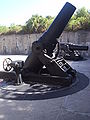
The M1890M1 mortar was most often installed on an M1896 carriage (as shown here in the images at top left and right). The mortar and its carriage weighed a total of 78.5 tons. The carriage was geared to enable it to be turned (in azimuth) by means of a traversing crank with two handles, located on the right side of the piece. A ring marked in degrees of azimuth ran around the mortar, just outside the inner steel circle or "racer" that carried the carriage, and a soldier read a pointer on the racer to aim the mortar in direction. The tube was raised or lowered (in elevation) by twin geared wheels with long spokes (resembling ship's wheels) that were located on either side of the carriage. The breech could be rapidly depressed to an almost level position for loading and then be quickly elevated for firing.
In addition to the elevation of its tube, the factor that determined the mortar's range was the size of the powder charge that was loaded into its breech, following the shell. The desired range for the mortar was specified in terms of zones. The smallest zone (shortest range) was Zone 1, and the largest (longest range) was Zone 9. With the so-called "aliquot charge" (shown in the photo at right), up to 9 equal-sized, disk-shaped bags of powder (each about 2 inches (5.1 cm) thick and containing 6.3 pounds (2.9 kg) of powder) could be attached to a 10th (or "base") bag, by means of cloth binding straps that were sewn to the base bag. Often the base bag was painted red, indicating that the powder assembly was to be loaded into the breech "red end last," so that it bumped up against the closing breech block (or faced the gunner). The red base bag also contained a small charge of black powder as an igniter. When the breech was closed, a detonator was inserted through the breech block and contacted the igniter, ready to set off the full powder charge.
The mortar could be fired in one of two ways: either electrically or manually (by the pull of a lanyard). And each method had its own type of detonator (electrical or friction). Electrical firing required first that the crew attach a wire to the electrical detonator, which protruded from the breech block. Second, the crew had to connect the firing cable coming out of the pit floor to the carriage of the individual mortar, out in the pit. Third, the circuit switch (usually located on the wall of the pit near the data booth) leading to the individual mortar had to be thrown into the closed (firing) position. Finally, the firing magneto, which was mounted on a special "shoe", often on the wall of the pit near the data booth, had to be cranked up and then released, sending the firing current out to the pit. Depending on the switch settings, the mortars in a given pit could be fired one at a time or all together. Lanyard firing had fewer fail-safe features, and was accomplished by a crewman who stood well behind the breech and pulled smartly on the lanyard to fire the individual mortar.
, the Army engineer who invented the design, Abbot Quads were rectangular configurations of four rectangular mortar pits, with each pit designed to mount four of the huge mortars. A plan for an Abbot Quad mortar battery is shown at left.
The idea behind the Abbot Quad was to have all 16 mortars in the four pits fire at once, producing a shotgun-like salvo of plunging shells optimally dispersed to destroy an enemy ship. It was argued that targeting each mortar individually would not produce many more hits than salvo firing, since early fire control procedures and equipment were often error-prone. Furthermore, proponents of salvo firing pointed out that it made for easier command and control (particularly under battle conditions), since all mortars in all pits of a battery could be given the same firing data. Early battery designs often contained one central "firing room" from which cables ran out to the various mortar pits, enabling electrical firing of all weapons simultaneously.
However, the early Abbot Quad designs featured very small mortar pits. Often, four mortars were mounted in a pit that was only about 40 by in size. Four circular areas about 18 feet (5.5 m) in diameter would fit into one of these early pits, producing a very crowded situation (given that two adjacent M1890 mortars mounted in such a pit would have their muzzles almost touching if they were traversed to face each other). A photo of such an early "crowded pit" is shown at left.
When a mortar battery was fully manned, formal guidelines called for a pit containing just two mortars (see photo at right) to be manned by a pit commander, two mortar squads of 17 enlisted men each, and an ammunition squad of 16 enlisted men. One of the last versions of the manual for the 12-inch mortar gives details on how it was to be crewed and fired.
After about 1905, reliance on the Abbot Quad design declined. Some artillery officers argued strongly that salvo firing was inherently wasteful, and that a much better hit ratio could be achieved by aiming each mortar individually against a specified target. They also argued that the smaller, cramped mortar pits of the early Abbot Quad battery designs were simply too crowded for efficient operations, with mortar crews for different tubes constantly getting in each others' way.
As fire control methods improved and the network of base end station
s was extended, from about 1905 on, individual aiming of mortars could be more accurate. At the same time, designs for new pits often specified only two mortars per pit, and many forts constructed their mortar pits side-by-side. Many 4-mortar pits were "depopulated," and some of their tubes were sent away to equip newer batteries. The Abbot Quad designs passed from favor.
In 1930 the US Army tested 12 inch mortars that were train based that could be moved to different locations of the country in a time of crisis.
The film shows the heavy shells (on shell carts) being wheeled up to the breeches of the mortars and being rammed home, the powder bags being tossed into the breeches after them, the crew clearing the immediate area while the chief of the breech raises his arm to indicate "ready to fire," and the mortars being fired electrically (from outside the area pictured). The tubes and then depressed, crewmen rush back in to swab out the tubes, the tubes are elevated, and crewmen back off ("taking cover"), firing occurs, and the process repeats itself.
The shock wave from firing just one of these huge mortars, particularly if it was fired within one of the smaller, old-style pits, was often so strong that it destroyed sensitive equipment mounted near the pit, knocked doors off of nearby magazines and barracks buildings, and broke windows in neighborhoods that were near the mortar batteries. The thundering crash of four of these mortars being fired simultaneously in a pit must have been overwhelming.
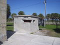 The images here show another feature of the mortar pits—the data booth. Personnel in this small space, with its tapered viewing slits, received the coordinates (azimuth and elevation) that had been calculated via plotting board
by the battery's Range Unit as the firing coordinates for the mortars in order for them to hit their targets.
These booths were either small, free-standing structures, about 10 feet (3 m) square and 7 feet (2.1 m) tall (as shown here in the topmost photos), or were built into one of the walls of the mortar pit itself (lower photo at right). The reconstructed data board in the photo at left hangs off the side of the data booth and is used to post the firing coordinates for mortars #3 and #4 in its pit (evidently the only two mortars there). The "Zone" number posted on the board refers to the size of the powder charge to be loaded for the coming shot (as discussed above). The top photo at right shows a decomposed set of slats (which likely used to have slates attached to them) that could have firing data chalked onto them and then be slid out of the data booth so they could be seen by the mortar crews in the pit.
Since crews of the mortars could not see their targets, they were especially dependent on the overall fire control system
, with its base end station
s and plotting room
, to locate and pinpoint targets for them to hit.
Endicott Board
Several boards have been appointed by US presidents or Congress to evaluate the US defensive fortifications, primarily coastal defenses near strategically important harbors on the US shores, its territories, and its protectorates.-Endicott Board:...
set forth its plan for upgrading the coast defenses of the United States, it relied primarily on mortars, not guns, to defend American harbors. Over the years, provision was made for fortifications that would mount some 476 of these weapons, although not all of these tubes were installed. Today, the only remaining mortars of this type in the 50 states exist at Battery Laidley, part of Fort Desoto in Florida, but the remains of coast defense mortar emplacements can be seen at many Coast Artillery forts across the United States and its former territories.
The weapons
This mortar, and its later model, the M1908 usually fired deck-piercing (also called armor-piercing) shells. These weighed from 700 to 1046 lb (317.5 to 474.5 ) and had heavy, hardened steel caps, designed to pierce a ship's deck armor before the shell exploded. These mortars, firing the half-ton shells at an elevation of 45 degrees, had a range of 12019 yards (11 km) (about 7 miles).
The deck-piercing shells were usually the ammunition of choice, because even the heaviest battleships of the 1890-1920 period were relatively lightly armored on the tops of their main decks, so a plunging half-ton shell could inflict crippling damage on one of them. Early on (from about 1890 to 1915), coast defense mortars were also supplied with so-called "torpedo shells" weighing 800 or. (see illustration at right, below). These were thin-walled shells roughly 5 feet (1.5 m) in length that carried explosive charges of about 130 pounds (59 kg) and were meant to detonate upon contact with the deck of a ship, scattering fragments among the crew.
The M1890M1 mortar was most often installed on an M1896 carriage (as shown here in the images at top left and right). The mortar and its carriage weighed a total of 78.5 tons. The carriage was geared to enable it to be turned (in azimuth) by means of a traversing crank with two handles, located on the right side of the piece. A ring marked in degrees of azimuth ran around the mortar, just outside the inner steel circle or "racer" that carried the carriage, and a soldier read a pointer on the racer to aim the mortar in direction. The tube was raised or lowered (in elevation) by twin geared wheels with long spokes (resembling ship's wheels) that were located on either side of the carriage. The breech could be rapidly depressed to an almost level position for loading and then be quickly elevated for firing.
In addition to the elevation of its tube, the factor that determined the mortar's range was the size of the powder charge that was loaded into its breech, following the shell. The desired range for the mortar was specified in terms of zones. The smallest zone (shortest range) was Zone 1, and the largest (longest range) was Zone 9. With the so-called "aliquot charge" (shown in the photo at right), up to 9 equal-sized, disk-shaped bags of powder (each about 2 inches (5.1 cm) thick and containing 6.3 pounds (2.9 kg) of powder) could be attached to a 10th (or "base") bag, by means of cloth binding straps that were sewn to the base bag. Often the base bag was painted red, indicating that the powder assembly was to be loaded into the breech "red end last," so that it bumped up against the closing breech block (or faced the gunner). The red base bag also contained a small charge of black powder as an igniter. When the breech was closed, a detonator was inserted through the breech block and contacted the igniter, ready to set off the full powder charge.
The mortar could be fired in one of two ways: either electrically or manually (by the pull of a lanyard). And each method had its own type of detonator (electrical or friction). Electrical firing required first that the crew attach a wire to the electrical detonator, which protruded from the breech block. Second, the crew had to connect the firing cable coming out of the pit floor to the carriage of the individual mortar, out in the pit. Third, the circuit switch (usually located on the wall of the pit near the data booth) leading to the individual mortar had to be thrown into the closed (firing) position. Finally, the firing magneto, which was mounted on a special "shoe", often on the wall of the pit near the data booth, had to be cranked up and then released, sending the firing current out to the pit. Depending on the switch settings, the mortars in a given pit could be fired one at a time or all together. Lanyard firing had fewer fail-safe features, and was accomplished by a crewman who stood well behind the breech and pulled smartly on the lanyard to fire the individual mortar.
How the mortar emplacements were designed
The earliest coast defense mortar batteries of the modern era were designed (starting in about 1892) as so-called "Abbot Quads". Named for Gen. Henry Larcom AbbotHenry Larcom Abbot
Henry Larcom Abbot was a military engineer and officer in the United States Army.-Early life:Henry Larcom Abbot was born in Beverly, Massachusetts. Abbot attended West Point and graduated second in his class with a degree in military engineering in 1854...
, the Army engineer who invented the design, Abbot Quads were rectangular configurations of four rectangular mortar pits, with each pit designed to mount four of the huge mortars. A plan for an Abbot Quad mortar battery is shown at left.
The idea behind the Abbot Quad was to have all 16 mortars in the four pits fire at once, producing a shotgun-like salvo of plunging shells optimally dispersed to destroy an enemy ship. It was argued that targeting each mortar individually would not produce many more hits than salvo firing, since early fire control procedures and equipment were often error-prone. Furthermore, proponents of salvo firing pointed out that it made for easier command and control (particularly under battle conditions), since all mortars in all pits of a battery could be given the same firing data. Early battery designs often contained one central "firing room" from which cables ran out to the various mortar pits, enabling electrical firing of all weapons simultaneously.
However, the early Abbot Quad designs featured very small mortar pits. Often, four mortars were mounted in a pit that was only about 40 by in size. Four circular areas about 18 feet (5.5 m) in diameter would fit into one of these early pits, producing a very crowded situation (given that two adjacent M1890 mortars mounted in such a pit would have their muzzles almost touching if they were traversed to face each other). A photo of such an early "crowded pit" is shown at left.
When a mortar battery was fully manned, formal guidelines called for a pit containing just two mortars (see photo at right) to be manned by a pit commander, two mortar squads of 17 enlisted men each, and an ammunition squad of 16 enlisted men. One of the last versions of the manual for the 12-inch mortar gives details on how it was to be crewed and fired.
After about 1905, reliance on the Abbot Quad design declined. Some artillery officers argued strongly that salvo firing was inherently wasteful, and that a much better hit ratio could be achieved by aiming each mortar individually against a specified target. They also argued that the smaller, cramped mortar pits of the early Abbot Quad battery designs were simply too crowded for efficient operations, with mortar crews for different tubes constantly getting in each others' way.
As fire control methods improved and the network of base end station
Base end station
Base end stations were used by the U.S Coast Artillery as part of fire control systems for locating the positions of attacking ships and controlling the firing of seacoast guns, mortars, or mines to defend against them....
s was extended, from about 1905 on, individual aiming of mortars could be more accurate. At the same time, designs for new pits often specified only two mortars per pit, and many forts constructed their mortar pits side-by-side. Many 4-mortar pits were "depopulated," and some of their tubes were sent away to equip newer batteries. The Abbot Quad designs passed from favor.
In 1930 the US Army tested 12 inch mortars that were train based that could be moved to different locations of the country in a time of crisis.
Firing the mortars
The Coast Defense Study Group (CDSG) has found and posted this unique film clip that dates from around 1915 and shows (during its first 3 minutes or so) a firing drill on the 12-inch mortars of Battery Howe, part of the harbor defenses of San Francisco. Although the battery shown is a linear one, the firing drill is similar to what would have taken place in a square or rectangular pit.at Fort Banks. The film clip clearly illustrates how congested one of the old-style pits would have become if used to fire four mortars simultaneously (or nearly so).The film shows the heavy shells (on shell carts) being wheeled up to the breeches of the mortars and being rammed home, the powder bags being tossed into the breeches after them, the crew clearing the immediate area while the chief of the breech raises his arm to indicate "ready to fire," and the mortars being fired electrically (from outside the area pictured). The tubes and then depressed, crewmen rush back in to swab out the tubes, the tubes are elevated, and crewmen back off ("taking cover"), firing occurs, and the process repeats itself.
The shock wave from firing just one of these huge mortars, particularly if it was fired within one of the smaller, old-style pits, was often so strong that it destroyed sensitive equipment mounted near the pit, knocked doors off of nearby magazines and barracks buildings, and broke windows in neighborhoods that were near the mortar batteries. The thundering crash of four of these mortars being fired simultaneously in a pit must have been overwhelming.
Fire control
Plotting board
A plotting board was a mechanical device used by the U.S. Coast Artillery to track the observed course of a target , project its future position, and derive the uncorrected data on azimuth and range needed to direct the fire of the guns of a battery to hit that target...
by the battery's Range Unit as the firing coordinates for the mortars in order for them to hit their targets.
These booths were either small, free-standing structures, about 10 feet (3 m) square and 7 feet (2.1 m) tall (as shown here in the topmost photos), or were built into one of the walls of the mortar pit itself (lower photo at right). The reconstructed data board in the photo at left hangs off the side of the data booth and is used to post the firing coordinates for mortars #3 and #4 in its pit (evidently the only two mortars there). The "Zone" number posted on the board refers to the size of the powder charge to be loaded for the coming shot (as discussed above). The top photo at right shows a decomposed set of slats (which likely used to have slates attached to them) that could have firing data chalked onto them and then be slid out of the data booth so they could be seen by the mortar crews in the pit.
Since crews of the mortars could not see their targets, they were especially dependent on the overall fire control system
Coast Artillery fire control system
In the U.S. Coast Artillery, the term fire control system was used to refer to the personnel, facilities, technology and procedures that were used to observe designated targets, estimate their positions, calculate firing data for guns directed to hit those targets, and assess the effectiveness of...
, with its base end station
Base end station
Base end stations were used by the U.S Coast Artillery as part of fire control systems for locating the positions of attacking ships and controlling the firing of seacoast guns, mortars, or mines to defend against them....
s and plotting room
Plotting room
A plotting room was used by the U.S. Coast Artillery to house a team of soldiers who were engaged in controlling fire for the guns of a Coast Artillery battery...
, to locate and pinpoint targets for them to hit.
See also
- Battery WayBattery WayBattery Way, named after Lt. Henry N Way of the 4th U.S. Artillery, is a battery of four 12-inch mortars on the Island of Corregidor. This was the only single-pit battery built as part of the expansion of the U.S. Coast Artillery, and was constructed during the period 1904-1910...
- List of heavy mortars
- List of U.S. Army weapons by supply catalog designation SNL E-13